 |
Audio Line In and Out
To download this page as a word document click here.
Although
there are numerous posts about the audio line in and out on the web I found that
none of them went into the topic as thoroughly as I needed. I tried the common
hack using the voice outputs from the Yamaha chip and running that into an op
amp for amplification. This method
seemed adequate for most applications but didn't support midi output. The only
thing that I could get to come out of the voice outputs was wave files. I also
wanted to make full use of the Yamaha driver functions including 3D Wide and
volume control. I also wanted to do it correctly according to the specification
of the LM4835. To accomplish these tasks I had to trace out the Audio portion of
the I-Opener and generate a schematic. This schematic can be found in figure
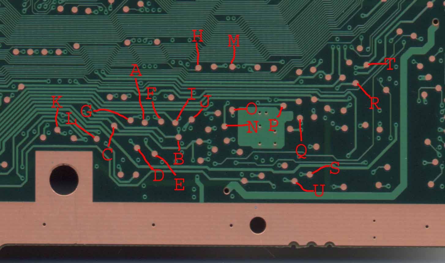
1 below. The letters outside the Yamaha chip refer to test points on the
underside of the I-Opener motherboard. I included this information to aide in
soldering to the I-Opener. To find where these test points are on the
motherboard refer to picture 1. Please also note that the schematic shows
several resistors and capacitors that were not installed n my I-Opener. These
components are listed below:
| R6 | R115 | C2 |
| R9 | R103 | C3 |
| R8 | R120 | C5 |
| R10 | R159 | C9 |
| R97 | R168 |
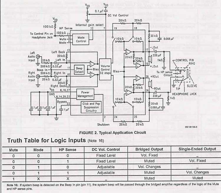
I was unable to determine where the unconnected end of resistors R159 and R166 went. The resistors that were installed have their component values listed on the schematic. The capacitors didn’t have their values marked on them and I didn’t feel like measuring them all, thus their values aren’t listed. It’s interesting to compare the I-Opener schematic to that in excerpt 2, which is the typical application of the LM4835 as written by National Semiconductor.
Several people have noted that the I-opener seems to be doing some sort of mixing with the Left and right channel outputs, which is why everyone is using the voice outputs instead. First of all these people are right, but this can be fixed. If you install the Yamaha drivers you can change how the Yamaha chip does "surround" or even turn it off. It's the slider bar labeled 3D Wide. If you turn this OFF (check the mute box) then you dramatically reduce the amount of mixing between the channels but it's not removed altogether. To remove the channel mixing altogether you have to remove a resistor in the audio output section between the Yamaha chip and the LM4835 chip. Although you can remove the whole mixing circuit I just removed R167 and left the rest of the components installed. Again refer to figure 1 to understand which resistor I'm talking about. By removing this resistor and muting the "surround" in the volume control window you completely eliminate all of the mixing between channels.
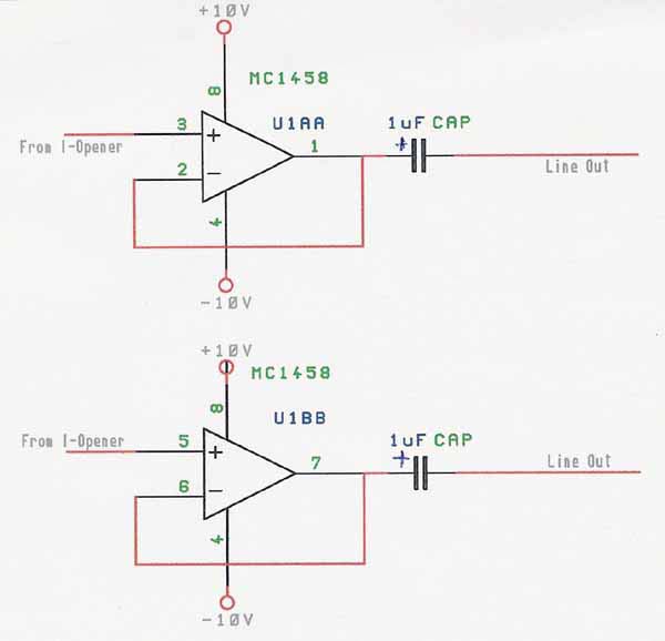
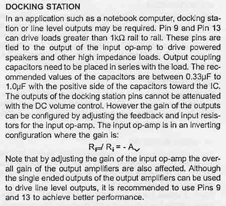
Now that I had a good quality signal the problem was making it into a line output signal. I tried two methods, one by placing caps on pins 9 and 13 on the LM4835 amplifier chip and running that directly to my stereo as a line out. This method is explained briefly on page 11 of the LM4835 amplifier chip document, document 1,and also in excerpt 1 below. I used .47uF capacitors for this method. The other method was to take the output directly from the Yamaha chip at pins 81 and 82, run that through an op amp buffer then to my stereo. Refer to figure 2 to see what my op amp buffer consisted of. Please note that the power listed to the op amp is +10V and -10V. This is not a misprint. I needed to use a +- power supply to the op amp to get the op amp to achieve 0V output. With only a single ended 5V supply the minimum my op amp could output was about 2V which caused the output of the op amp to clip the sine wave at his level, not cool. Since the sine wave going into the op amp is offset by 2.5VDC I could only get a perfect sine wave with a peak voltage of .5V. To get a full 1V peak out of the op amp I would need an op amp capable of 1.5V out or less. To make a long story short instead of changing my op amp selection I used a bipolar supply and didn't care if the signal could only go to -8V out of -10V because it never went negative anyway. Where did I get +- 10V? I got creative and stole it from my unused pins on my serial port. I used a Sipex SP235 (Identical to MAX235) to enable my serial port. There were two unused RS232 pins. I just tied their associated TTL inputs one to ground the other to +5V. The SP235 can supply plenty of current to power my op amp. Looking at the Sipex SP235 document, document 2 I found that the SP235 can supply better than 4mA at 6V. This amount of current would allow a line output to have a resistance down to 250 ohms. If for some reason you short out the line output the SP235 would current limit without damage before the op amp would current limit. This could however interrupt any serial data being transmitted.
To make things easier for yourself I would recommend that you find an op amp that allows for a lower voltage threshold so that you can use a single ended 5V supply. I know that the LM324 will operate down to 0V and should be a good choice for an op amp except that it has 4 op amps and is in a 14 pin dip package.
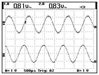
To test each configuration I ran an audio input to the line input of the Yamaha chip. I did this by placing a 1uf capacitor in series between the line input pins 85 and 86, and my audio out on my PC. I set my PC up to generate a sine wave of varying frequencies and recorded the input waveform to the Yamaha chip and the waveform from my line out configuration. I generated two graphs of gain versus frequency and plotted them logrithmatically. The data that I collected can be found in chart 1 below. The two graphs that I generated from this data can be found in graph 1 below. The first column shows the frequency of the measurement. The second column shows the input RMS voltage out of my PC’s sound card. The third column shows the output voltage of the I-Opener using that line out method. The fourth column is just output divided by input voltage. The fifth column is the “normalized” gain. It’s the gain divided by the highest gain in the fourth column. If you haven’t noticed, the chart shows the input voltage dropping drastically at high frequencies. With a –3dB of about 11KHz. That’s the response of my sound card on my PC. When I saw that I got disgusted with the crappy response. This doesn’t affect my I-Opener measurements because I am looking at gain and not voltage. The graphs were generated using the frequency and the normalized gain. The two graphs that I generated from this data can be found in graph1A below. To see how I took the measurements for chart 1 refer to picture 2. Channel A is the input voltage and channel B is the output voltage.
The first graph, graph 1A shows the response of my op amp approach using the approach previously described. The second graph, graph 1B shows the response of my non op amp approach also previously described. As it is obviously clear, the op amp gives a much better response than the non op amp approach. The –3dB points for the op amp approach are somewhere outside my 20Hz to 20KHz test range. The –3dB point for the non op amp approach is not, at about 30Hz. By looking at the schematic in figure 1 it seems that this is caused by the small value of capacitors C92 and C100. I measured their value in circuit to be about .33uF. In case you’re wondering if the .47uF capacitors on the line inputs that I used on pins 9 and 13 of the LM4835 caused the poor frequency response, I did remove the “load” by disconnecting my stereo from the line out configuration and noticed no change in frequency response.
For those of you that want a headphone output I didn’t do any tests on this. One way that I can see to accomplish this is to connect an LM386 amplifier to pins 81 and 82. This way you will be ensured a good quality signal to the amplifier, assuming you remove either R167, R158, C106, or C107.
Another method you could use if you don’t want to mount another circuit board in your I-Opener is to use the method described in the LM4835 document. Refer to excerpt 2 and document 1. If you don’t want to ever use the original speakers then you could ignore the headphone sense input and just disconnect the speaker connectors. Looking at the schematic in excerpt 2, you will have to add a 220uF cap and a 1K resistor for each channel. Using the right channel as an example you could do the following:
Install a 220uF cap in place of R97 (which is not installed)
Install the 1K resistor in place of C3 (which is not installed)
Install jumper wires or 0 ohm SMD resistors to resistors R8 and R10 (which are not installed)
This will give you a headphone output at connector CN1 which just happens to be located on the same small skinny circuit board that the volume control and power button are located. It seems that the I-Opener was designed with some sort of line out or headphone out option but was never installed. If you don’t want to work with SMD parts then maybe the best solution is to mount your non SMD cap and resistor to the bottom of the circuit board on pads R and S (Pins 17 and 26 of the LM4835). If you want to go all out and have the original speakers operational and cut out when you plug the headphone jack in then you need to connect up the headphone sense option. Pin 21 is already connected to a 100K resistor but unfortunately it’s connected to ground not 5V. You’ll have to remove this resistor and connect two 100K resistors as indicated in except 2. All this said the best you can achieve with this configuration is the –3dB of 30Hz because that’s the input signal to the LM4835 amplifier. If you have headphones with better response than that then you might want to look into increasing the size of C92 and C100 or maybe the LM386 amplifier method. I haven’t tried any of these headphone configurations but I’ll take National Semiconductors word that it’ll work.
It seems that people are going to ask questions about what type of impedance my op amp line out method can withstand. It seems that a lot of stereos have about 1K of impedance but some have more or less. To help alleviate the concern I tested my op amp line out with a 330 ohm resistor and found no attenuation. So the answer to the question is, don’t worry about it.
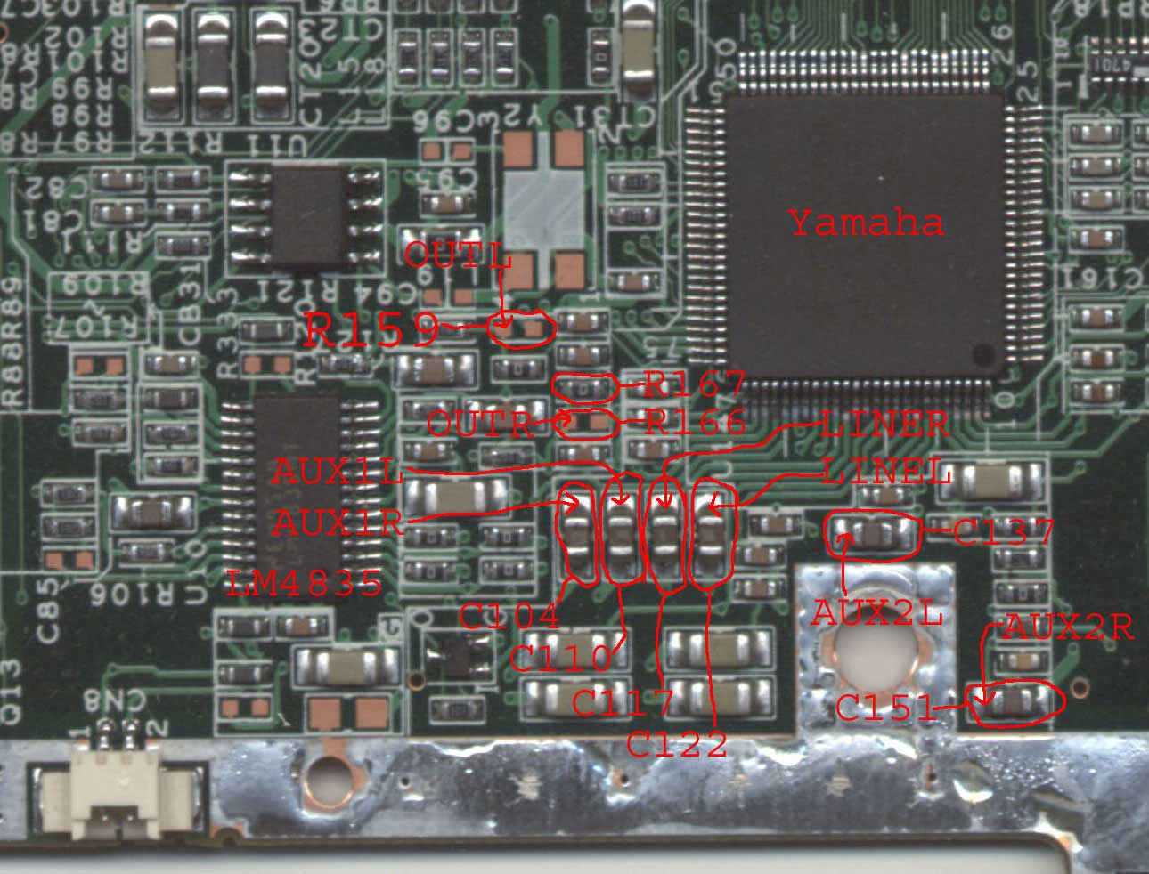
OK now that we know just what’s going on with the audio in the I-Opener what do I recommend for a line out? Well if you can live with the –3dB of 30Hz then the easiest solution is to place .47-1uF caps on pins 9 and 13 of the LM4835 and connect them to the line out. If you want the best quality possible then I recommend you use the op amp method that I used. Or rather I recommend that you use a different op amp similar to a LM324. There is nothing wrong with using the LM324 except that it’s a little bigger physically and has two extra (4 total) op amps that you won’t need. I guess the good thing is that it’s available at Radio Shack. As for the best place to solder to the I-Opener, I’d recommend to solder to R159 and R166 to tap pins 81 and 82 on the I-Opener. These resistors are not installed and their pads are easily accessible, or rather relatively accessible as far as SMD parts go. Refer to picture 3 for the location of these parts and which pads to solder to. For the Line input and for the AUX1 input I would recommend soldering to the capacitor as indicated by picture 3. As for AUX2 I’m undecided as to whether it’s easier to solder to the capacitor or to the bottom of the circuit board. For pins 9 and 13 I’d recommend soldering to the bottom of the circuit board. Also note that I’ve circled R167 so you can locate it easier for removal. Hey, need any spare 0 ohm resistors for the second USB port mod? Above all, if you aren’t proficient with soldering to surface mount components then I’d stay away from soldering to the component side of the circuit board. If you mess up soldering to the bottom side there is less chance to destroy stuff. It’s a good idea to make some sort of strain relief for all your line in and line out wires that get soldered to the circuit board. The pads on the circuit board, both top and bottom are small and if you snag a wire while working on your next mod then you could easily rip an entire component or pad from the circuit board. I used a 22AWG bare wire and fashioned a loop with both ends soldered to the copper ground plane on the edge of the circuit board. I then tied all of my wires to that loop of wire.
The material used for reference in the production of this document include:
Document 1: The LM4835 amplifier by National Semiconductor: LM4835.PDF
Document 2: The Sipex SP235 multi channel RS232 driver/receiver by Sipex: SP235.PDF
Document 3: The Yamaha YMF715E sound chip by Yamaha 4MF715E20.PDF
All of the tests that I performed were done with the following equipment:
Fluke 87 IV multimeter (capacitance measurement)
Fluke 192 Scopemeter (all other measurements)
Ensoniq AudioPCI S5016 with the ES1370 chipset (used to generate sine waves to inject into the I-Opener) This sound card was made just before Creative Labs bought out the rights for this card from Ensoniq, renamed it, and doubled the price. Now it’s an older card and no longer sold by creative labs.
|
 |
 |
 |
|
Op Amp
Configuration |
|
|
|
|
|
Frequency
(Hz) |
Input
(V) |
Output
(V) |
Raw
Gain |
Gain |
|
20 |
0.68 |
0.72 |
1.0588 |
0.9823 |
|
40 |
0.77 |
0.83 |
1.0779 |
1.0000 |
|
60 |
0.8 |
0.85 |
1.0625 |
0.9857 |
|
80 |
0.81 |
0.86 |
1.0617 |
0.9850 |
|
100 |
0.81 |
0.86 |
1.0617 |
0.9850 |
|
200 |
0.81 |
0.86 |
1.0617 |
0.9850 |
|
400 |
0.81 |
0.85 |
1.0494 |
0.9735 |
|
500 |
0.81 |
0.84 |
1.0370 |
0.9621 |
|
1000 |
0.81 |
0.83 |
1.0247 |
0.9506 |
|
2000 |
0.79 |
0.81 |
1.0253 |
0.9512 |
|
3000 |
0.77 |
0.78 |
1.0130 |
0.9398 |
|
4000 |
0.75 |
0.76 |
1.0133 |
0.9401 |
|
6000 |
0.69 |
0.71 |
1.0290 |
0.9546 |
|
8000 |
0.63 |
0.65 |
1.0317 |
0.9572 |
|
10000 |
0.58 |
0.59 |
1.0172 |
0.9437 |
|
12000 |
0.52 |
0.54 |
1.0385 |
0.9634 |
|
14000 |
0.47 |
0.49 |
1.0426 |
0.9672 |
|
16000 |
0.43 |
0.45 |
1.0465 |
0.9709 |
|
18000 |
0.38 |
0.4 |
1.0526 |
0.9766 |
|
20000 |
0.313 |
0.332 |
1.0607 |
0.9840 |
|
|
|
|
|
|
|
Without Op Amp
Configuration |
|
|
||
|
Frequency
(Hz) |
Input
(V) |
Output
(V) |
Raw
Gain |
Gain |
|
20 |
0.86 |
0.54 |
0.6279 |
0.6158 |
|
40 |
0.98 |
0.86 |
0.8776 |
0.8607 |
|
60 |
1 |
0.96 |
0.9600 |
0.9415 |
|
80 |
1.01 |
1 |
0.9901 |
0.9711 |
|
100 |
1.02 |
1.02 |
1.0000 |
0.9808 |
|
200 |
1.02 |
1.04 |
1.0196 |
1.0000 |
|
400 |
1.02 |
1.03 |
1.0098 |
0.9904 |
|
500 |
1.02 |
1.03 |
1.0098 |
0.9904 |
|
1000 |
1.02 |
1.01 |
0.9902 |
0.9712 |
|
2000 |
0.99 |
0.98 |
0.9899 |
0.9709 |
|
3000 |
0.97 |
0.95 |
0.9794 |
0.9606 |
|
4000 |
0.93 |
0.91 |
0.9785 |
0.9597 |
|
6000 |
0.85 |
0.83 |
0.9765 |
0.9577 |
|
8000 |
0.77 |
0.75 |
0.9740 |
0.9553 |
|
10000 |
0.7 |
0.68 |
0.9714 |
0.9528 |
|
12000 |
0.62 |
0.61 |
0.9839 |
0.9650 |
|
14000 |
0.56 |
0.55 |
0.9821 |
0.9633 |
|
16000 |
0.51 |
0.49 |
0.9608 |
0.9423 |
|
18000 |
0.46 |
0.44 |
0.9565 |
0.9381 |
|
20000 |
0.38 |
0.37 |
0.9737 |
0.9550 |
Graph 1A Op Amp Configuration:
Graph 1B Without Op Amp Configuration:
 |
 |
 |
Legal stuff: