|
|
Welcome to my I-opener page. This page is dedicated to my progressing modifications to my Netpliance I-opener.
Modifications that I have made include:
Unique HDD installation allowing usage of the original heatsink.
Disabled the Sandisk.
SMC Ethernet modification internal to the I-Opener.
Dual serial port modification.
Unique Audio out and dual audio line inputs.
Soon (hopefully) to come modifications:
Automatic shutdown from serial port using APC software.
Custom micro mouse addition.
Keyboard interface to use the palm portable collapsible keyboard.
Here are some pictures of my I-opener after all the internal modifications have been made:
|
|
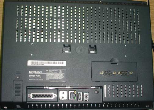
The back of my IO. It clearly shows the addition of both com 1 and com 2. I added an Ethernet port and a dual audio line in port in the place where the modem jacks were. Who needs a modem anyway? In the place where the second USB port was reserved for I placed my audio line out jack.
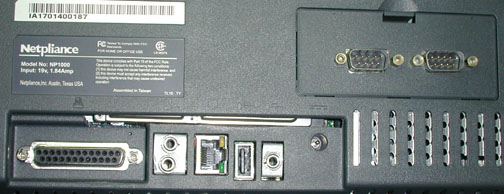 |
Here's a close up of the added jacks: You can also see my HDD peeking through the cutout. It was a close fit for my HDD installation. In retrospect I may not have had to make this cut out.
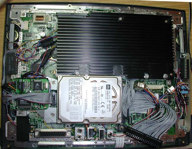 |
This is the inside of my IO prior to applying a large shoe horn to get the case back on... The HDD is easy to find, it's mounted on a piece of zinc plated steel. The circuit board of the SMC Ethernet adapter is also mounted on this steel. There is a cutout in the steel for the serial port connector. The large IC below the speaker in the left corner is the SIPEX serial converter. It's mounted on a circuit board below the motherboard. The barrel shaped things to the left of the heatsink are the caps for the audio inputs. They're black due to heat shrink... The two 9 pin com ports are just that, the com ports. The 40 pin IDC connector is for convenience. It will just sit behind the RAM door in case I want to plug a CDROM in temporarily. The vertically mountedboard on the right of the screen is the circuit board for the SIPEX serial converter for com 2. The board is also the home for the audio line out op amp. There's actually two op amp circuits on the board, I added the other for future expandability. At the bottom you can see the audio and Ethernet jacks...
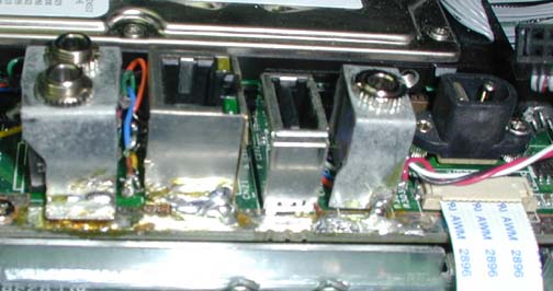 |
This shows how I mounted the ports. This side I soldered the ports directly to the ground plane. The ethernet adapter didn't quite make it to the ground plane so I uses an 18awg copper wire as"filler" material. I think you can see part of it tothe left of the solder joint. I had a hard time soldering these down even with a 100W soldering iron because I didn't want to melt the jacks already mounted inside. Looks like I used a little too much flux :( The other side of the jacks (not shown) was mounted by soldering two 22AWG wires to the metal and then in the holes previously occupied by the RJ11 ports. I was sure to cut the trace leading to these new "mounting" pads.
For extensive information on adding audio line inputs and outputs click here.